DFX Series electromagnetic pressure valve
一、 Purpose and structural characteristics:
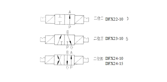
DFX22 type, DFX23 type, DFX24 type electromagnetic pressure valve system two two-way, two-way and four-way spool valve structure two. It uses a DC or AC with a contact position double solenoid control slide valve to vary the flow direction of the oil flow.
The valve system is used to control elements of water, fire, power plants and other industrial sectors of the hydraulic system, also used as a high flow valve pilot valve.
The solenoid valve using packaged magnet, and the slide valve with magnetic orientation, cancel the mechanical lock, so that greatly reduced power solenoid-operated slide valve commutation, to ensure reliable operation. Coil according to long-term power design, so that the coil is not easy to burn. On each side there are two pairs of electromagnets sealed contact, in order to ensure that the solenoid is energized to work instantaneously. And issued a valve position signal corresponding work to facilitate remote control.
The valve auxiliary functional and equipped with manual button and doubles as a working valve position indication, even in the absence of oil pressure situations, but also to manual or automatic operation for easy inspection.
The valve structure is simple, at the same flow rate, compared with other same type of valve has a small and stable and fast operating power corresponding characteristic, applicable to computer monitoring system.
二、Main technical data
1, working pressure: 2.5,4.0,6.3,21 Mpa
2, nominal diameter; Ø 10mm, Ø15mm
3, the working medium: the 20th and the 30th turbine oil
4, using the medium temperature: 5-60 ℃
5, the working voltage: 220V, 125V, 110V, 48V, 24V
AC 220V, 110V, 48V
6, Number of contacts: contacts on each side with two electromagnets
7,220V AC 220VA maximum or maximum 1A: contact capacity
DC 100W maximum when 220V or 0.5A maximum
8, coil power consumption: <25W, <40W
9, work: instantaneous energization
10, Connection: straight card sets of pipe joints
DFX22-10, DFX24-10 with G12
DFX23-15, DFX24-15 with G18
三、 Model description and notation
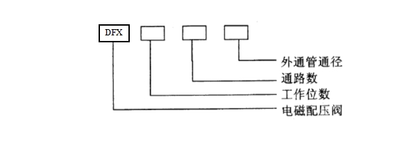
Example: DFX24-15 represent two-way, external tube diameter of 15mm of electromagnetic pressure valve.
Notation:
四、Installation, use and storage
After unpacking the valve, such as inspection found no abnormalities, the only check valve plug and body wash, generally do not have to break down. The valve must be installed horizontally, and the drain pipe joints (O) down the best, or at least at the site, so that the valve body can drain vent clean.
Before use of electromagnets insulation resistance should be checked and then press the system requires good line. When the solenoid valve with a DC power supply, you must press the icon "+", "-" pole wiring, otherwise the magnetic field generated by the coil is energized, the operation will have contacts magnet interference and affect the proper operation of the contact. Manual and automatic operation test, everything is working properly, can be put into operation.
Element if being not, should be injected into the internal anti-rust oil, and grease the exposed machined surfaces coated with anti-rust and stored in acid-free, alkali, salt and corrosive gases warehouse, from dust, rain and snow damage.
Users in custody, transportation, and comply with the conditions of use prescribed rules, from the date of shipment from the manufacturer or product two years in operation within a year (over period, whichever occurs first) due to poor manufacturing and damaged or not during normal operation, I plant responsible for maintenance and replacement.
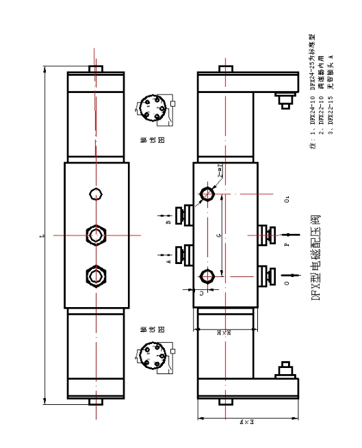
五、Dimensions



WSK-ZDB Temperature and humidity control
※Features
This product is a smart digital temperature temperature and humidity monitoring equipment. With a digital display of temperature setpoint and measured values, can change the work environment for real-time monitoring of temperature, start heating load of work when the cooling load circuit starts working when the ambient temperature is higher than the upper limit set value, the opposite is below the lower limit value, forcibly change the environment in which the temperature is controlled within the range set value; while the relative humidity and humidity monitoring unit for detecting changes in the surrounding environment, when humidity reaches a certain value, automatically connected to the load through an external load heating, ventilation, forced transformation of the media to reach the standard operating conditions until the condensation no longer occurs, the system is again in control state. Can effectively prevent all kinds of accidents due to moisture condensation caused. Its unique load break alarm output, can better ensure the unmanned supply system safe and efficient operation.
This product has high precision, small size, long life, easy to install, easy to use features.
※Main Specifications
Power supply:AC220V×(80~110%) 50Hz; Power consumption:4W
Conditions of Use:Temperature,-25℃~+60℃;
Humidity,Relative humidity≤93%RH
Temperature control: -50.0 ~ 150.0 ℃ adjustable
Control hysteresis: 0 ~ 20 ℃ adjustable
Kai control Humidity: 85% RH ± 5% (hysteresis 5% RH)
Accuracy: 0.5%±1个word
Temperature coefficient of less than 0.05% / ℃
Break alarm: Passive contact output (normally open), AC220V/3A,28VDC/10A
High voltage: 50Hz, 1500V AC lasted 1min, no breakdown and arcing phenomenaLoad
Capacity: rated power resistive load AC220V / 3A
Volume:72×72×116mm3 Weight:0.50Kg
※Supporting load electric heater: Power100W、150W、200W、300W、500W。
※Use Installation
1.Appearance and installation:
Embedded installation, opening size66+0.5×66+0.5mm2

1,2contact temperature sensor;3,4then condensation sensor;5,12then heating load;6,12then cooling load;7,13then condensation load;8,9contact temperature load break alarm;10,11then condensation load break alarm;13,14AC220V power connection。
3.Function Operation
The temperature unit commissioning instructions:According to the instructions take a good line, check and correct energized, the display window will show the measured value of the controlled object. Users should be set according to the actual situation, then use the (then press the button , the setting items on the panel indicates the chart corresponding indicator lights.) Set operation is as follows:
1 press the button , the indicator on the lower control panel lights, which can be set lower limit temperature Kai control point by ∧ or ∨ key, set the value in the digital display will show the window, after reaching the requirements, go to step (2) setting.
2 button at the lower limit of the control light is off , the lower panel on the back of poor indicator lights, press ∧ or ∨ button to set back the difference (setting range 0 ~ 20 ℃), after the completion of this setting, go to step (3).
3 press the button , the lower hysteresis light is off, then the upper limit of the indicator light on the control panel, press the ∧ or ∨ key to set the maximum temperature of Kai control point, after setup is complete, enter the first step (4).
4 Press the button , the upper limit of the control lights off, and now back to the difference between the upper limit on the panel indicator lights, press ∧ or ∨ button to set back the difference (setting range 0 ~ 20 ℃), when you meet the requirements to enter the first step (5).
Note: The upper limit minus the upper limit of hysteresis can not be less than the lower limit value plus the difference between the lower back, otherwise the window will appear the words "RSET", will have to start again set in the normal display state.
5 Press the button , the upper limit of hysteresis light is off, then the temperature correction indicator lights. Correction value has been set at the factory before, in general, do not modify this setting, in order to avoid the anti-amendment to the exact meter inaccuracies. When identified, including the control system includes a sensor error has occurred and can not get consistent results with higher precision level measurement device, you can use this product advanced "correction" feature, in order to reach agreement. (Setting: the temperature correction state, press ∧ or ∨ key to set the direction opposite to the one with the error to the same value within ± 10 range, the temperature values determined after the correction value displayed is the current temperature and the correction value and. if the current display temperature 26 ℃, tested high 3 ℃, the correction value can be set to -3, the revised display temperature 23 ℃;. whereas the opposite set) Press the button once
 to set the operation is complete, the device enters monitoring status.
6 After the equipment operation, concrete work follows:
① When the value of the measured temperature is less than the lower limit, the corresponding heating load starts, the lower indicator light; when the temperature rises, the value of the measured temperature is greater than the lower limit value and hysteresis and corresponding heating load to stop, the lower light off。
② When the value of the measured temperature is greater than the upper limit, corresponding to the cooling load starts, ceiling lights; when the temperature decreases, the value of the measured temperature is less than the upper limit of the return of poor poor, the corresponding cooling load is stopped, ceiling lights off. (As shown below)

7 Product testing. If the meter displays "----", please check the temperature sensor is short-circuited or not connected. If the above situation the instrument will automatically start protection function, the temperature load supply cut off, shall be excluded in order to use the fault. If you find the instrument abnormal work, you should check whether the range of the sensor wiring broken or shorted or temperature sensing element lead-reverse, check the monitor operating voltage and ambient temperature working conditions are prescribed.
8 Break alarm. When a unit of the apparatus is active, if the corresponding break alarm indicator light, corresponding alarm output terminal is also in the closed state, then the load wiring is off, please check the wiring load! Humidity unit detects Description: In automatic state, mouth Kazakh gas, proximity condensation sensor (the sensor can not be directly immersed in the water) for about five seconds, humidity indicator lights on the monitor, the work load; away from moisture, light off, load stop working, indicating condensation sensor is not damaged. Such as humidity unit starts when the load is disconnected, the disconnection warning indicator light and humidity, humidity alarm output end there.

Electrical contacts
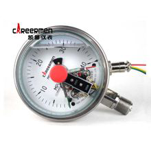
YXC100/150 Electrical contacts
Outline
YXC_00/150 Electrical contacts are widely used in petroleum, chemical, metallurgy, power plants and other industrial sectors or electromechanical equipment to measure various fluid pressure no explosion dangerous media. Typically, the instrument and the corresponding electrical devices such as relays and contactors, etc. supporting the use, can be measurement and control of pressure in the system to achieve the purpose of automatic control and transmission alarms.
YXC100/150 Electrical contacts not only novel design, reliable structure, full of different specifications, operation stability, adaptability of features, but also has monitoring and control, and Mao, simple installation, low maintenance, etc., so that it is generally no indication , the pressure controller without switching difference adjustment and no external setting device unmatched pressure measurement and control instruments.
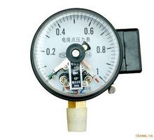
YXC-100 Electrical contacts
The principle instrument
Bourdon tube pressure measurement displaced by the gear mechanism, driven by the hands and moving and stationary contacts are connected or cut (upper or lower) causes the control circuit contacts and the set-off on the pointer to achieve automatic control and alarm signals purposes.
Technical Specifications and Features
Electrical contacts points YXC punch punch liquid solution and YXCN series, meter diameter Φ100 / 150mm
Accuracy class Φ100 / 150-1.6%
Measuring range 0-100MPa
Protection class YXC type IP54, YXCN type IP65
Electrical contacts using temperature -20 ℃ ~ 70 ℃
Working medium temperature 100 ℃
Working pressure upper limit of not more than two-thirds of the upper limit of the instrument
Work environment vibration frequency is not greater than 25Hz, the amplitude of less than 0.5mm
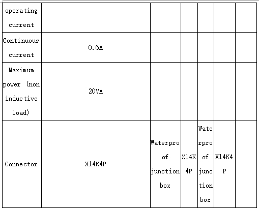
Scale range, accuracy levels and electrical parameters

Working pressure and use
Table circle Φ100 / 150mm: Static 3/4 × full scale
Dynamic pressure 2/3 × full scale
Instantaneous 1.3 × full scale
Maximum operating voltage A380V or DC220V
Maximum current 1A
Contact power 30VA
When the temperature temperature deviation from 20 ± 5 ℃ its set point error is not greater than 0.6% / 10 ℃.
YXC100 / 150 electrical contacts wiring diagram:
Magnetic-assisted electric contact pressure gauge
YXC magnetic electrical contacts pressure gauges are widely used in petroleum, chemical, metallurgy, power plants and other industrial sectors or electromechanical equipment to measure various fluid pressure no explosion dangerous media. Typically, the magnetic electrical contacts pressure gauge through the corresponding electrical devices (such as relays and contactors, etc.) supporting the use, it can aim the measured (controlled) pressure system to achieve automatic control and transmission (alarm) is.
